
ESP8266/ESP32 DevKit Pinouts
ESP8266 and ESP32 are among the most popular Wi-Fi-enabled microcontrollers used in IoT, DIY electronics, and embedded projects. Both chips are powerful, affordable, and widely supported — but understanding their pinouts and GPIO functions is crucial to avoid wiring mistakes and unexpected behavior. This guide covers the pinout diagrams, GPIO functions, and key considerations for both ESP8266 and ESP32 boards.
This guide covers the pinout diagrams, GPIO functions, and key considerations for both ESP8266 and ESP32 boards.
ESP-WROOM-32 Pinouts guide and usage hints
The ESP32 is a more powerful microcontroller than the ESP8266, offering more GPIO pins and a wider range of hardware interfaces. It also supports external Ethernet modules such as the LAN8720 via the RMII (Reduced Media Independent Interface).

Here’s a compact, practical ESP32 DevKit V1 pinout + the important “gotchas” and recommendations you’ll use most. I’ll call out the critical rules (boot/flash/ADC/touch/etc.) first so you don’t hit the usual traps.
Quick reference (useful defaults)
Power pins:
3V3(3.3 V regulator output),GND,EN(reset / enable). Many DevKit boards also expose aVIN/5Vfrom USB → regulator, but use 3.3 V for peripherals.USB-UART / Programming:
GPIO1 = TX0andGPIO3 = RX0are the serial console and used by the USB-to-UART for flashing/monitor. Avoid using them for critical hardware if you rely on serial prints/programming.I²C (common default):
SDA = GPIO21,SCL = GPIO22(you can remap if needed).SPI (typical VSPI hardware pins):
MOSI = 23,MISO = 19,SCK = 18,SS = 5. You may remap SPI using the GPIO matrix but these are the common defaults.DAC (analog out):
GPIO25,GPIO26— use these for true analog (DAC) output.PWM: Almost any GPIO can do PWM (LEDC) — except the input-only pins and flash pins (see next sections).
Pins you must not use / avoid or use carefully
SPI flash pins — GPIO6..GPIO11
These are connected to the module’s integrated SPI flash on WROOM/WROVER modules and must not be used for general I/O on DevKit modules. Using them will break the module.Input-only pins: GPIO34, 35, 36, 37, 38, 39
These pins are input only — they cannot be used as outputs and they don’t have internal pull-ups/pull-downs. Use external pull resistors if you need stable behavior.ADC constraints (ADC1 vs ADC2)
ADC1 channels are on
GPIO32–GPIO39and are safe to use while Wi-Fi is active.ADC2 channels (GPIO0,2,4,12–15,25–27) are shared with Wi-Fi drivers — don’t rely on ADC2 pins when Wi-Fi is used (they can behave unpredictably).
Boot / strapping pins — don’t pull them to the “wrong” level during reset
On ESP32 some pins are sampled at reset to decide the boot configuration. The important ones areGPIO0,GPIO2,GPIO5,GPIO12 (MTDI), andGPIO15 (MTDO)(behaviour differs slightly across ESP32 variants).GPIO0 low → enter UART download boot (used by flashing).
GPIO12 (MTDI) is special: if HIGH during reset it can change the flash power rail (VDD_SDIO) to 1.8 V, which will make most 3.3 V flash chips fail to boot (brown-out). Leave GPIO12 floating/pulled LOW unless you intentionally need 1.8 V.
If you wire external hardware to these pins, make sure they do not force the wrong level at power-on/reset.
Touch, RTC, and wake pins
Touch pins (capacitive): the ESP32 has 10 touch inputs mapped to GPIOs. Common mapping (T0..T9):
T0=GPIO4, T1=GPIO0, T2=GPIO2, T3=GPIO15, T4=GPIO13, T5=GPIO12, T6=GPIO14, T7=GPIO27, T8=GPIO33, T9=GPIO32. Touch pins are handy for wake-from-deep-sleep.RTC / deep-sleep wake pins: several GPIOs are routed to the RTC domain (e.g. GPIO36/39/34/35/25/26/33/32/4/0/2/15/13/12/14/27 depending on variant) — check the specific board docs for the exact set if you need ultra-low-power wake sources.
Practical rules & tips (short, actionable)
If in doubt, use these safe pins for general I/O:
GPIO4,GPIO16,GPIO17,GPIO18,GPIO19,GPIO21,GPIO22,GPIO23,GPIO25,GPIO26,GPIO27,GPIO32,GPIO33. (Avoid 6–11, and be careful with 0/2/12/15.)Use ADC1 for analog reads (
32–39) if you also need Wi-Fi. For ADC pins, add filtering and calibration — ESP32 ADCs are noisy and non-linear.Avoid connecting strong pull-ups/pull-downs to strapping pins — they affect boot. If you must use a strapping pin as regular I/O, add series resistors or ensure your external circuit is high-impedance at reset.
If you use I²C/I²S/SPI for peripherals, prefer the default pins (I²C 21/22, VSPI 23/19/18/5) first — they’re well supported in libraries. You can remap using the GPIO matrix if necessary.
Buttons on input-only pins: remember those pins lack internal pull resistors — add an external pull-up/down.
✅ Correct behavior of GPIO4
GPIO4 is not actually a boot strapping pin on most ESP32 variants (e.g., ESP32-WROOM-32, ESP32-WROVER).
It is sampled at boot on some very early or special ESP32 revisions (engineering samples, ESP32-D2WD), but in all common DevKit V1 and WROOM/WROVER modules, it behaves as a normal GPIO.
So in practice:
👉 GPIO4 is safe for general I/O, digital in/out, or peripheral functions.
It’s not like GPIO0, GPIO2, GPIO12, or GPIO15 — those truly affect boot mode.
🧩 Why confusion exists
Espressif’s original documentation listed GPIO4 among “strapping” candidates because:
It can serve as
MTDIin some alternate configurations, andIt’s also one of the touch sensor pins (T0), which caused overlap in early datasheets.
But in current ESP32 DevKit V1 boards (and Arduino/ESP-IDF defaults):
GPIO4 is not sampled for boot mode,
it’s not reserved by flash or PSRAM,
and it’s one of the safest general-purpose pins available.
✅ Summary Table (updated)
| Pin | Boot function | Safe for I/O? | Notes |
|---|---|---|---|
| GPIO0 | Boot mode select (low → download mode) | ⚠ Only if left high at reset | |
| GPIO2 | Must be LOW at boot | ⚠ Avoid pulling HIGH | |
| GPIO4 | (no longer used for boot) | ✅ Safe | |
| GPIO5 | Used as VSPI SS; may affect boot if LOW | ⚠ Safe if high/floating at reset | |
| GPIO12 (MTDI) | Changes flash voltage (dangerous) | ❌ Avoid | |
| GPIO15 (MTDO) | Must be LOW at boot | ⚠ Avoid external pull-ups |
Quick cheat-sheet (condensed)
Don’t touch:
GPIO6..GPIO11(flash)Input only:
GPIO34..GPIO39Serial console:
GPIO1 (TX), GPIO3 (RX)Default I2C:
SDA=21,SCL=22Default SPI (VSPI):
MOSI=23,MISO=19,SCK=18,SS=5DAC:
GPIO25,GPIO26ADC1 (safe with Wi-Fi):
GPIO32..GPIO39Strapping to watch:
GPIO0, GPIO2, GPIO5, GPIO12, GPIO15(don’t force levels at boot)
(References: Espressif datasheets / docs + community pinout references and tutorials.) (espressif.com)
ESP8266MOD ESP-12F ESP-S D1 mini Pinouts guide and usage hints
The ESP8266 is one of the most popular Wi-Fi chips for IoT projects. While modules like the ESP-12F, ESP-07, and other ESP8266 variants provide only a limited number of usable pins, development boards and breakout boards make it much easier to access these GPIOs in your designs.

The ESP8266 is one of the most popular Wi-Fi chips for IoT projects. While modules like the ESP-12F, ESP-07, and other ESP8266 variants provide only a limited number of usable pins, development boards and breakout boards make it much easier to access these GPIOs in your designs.
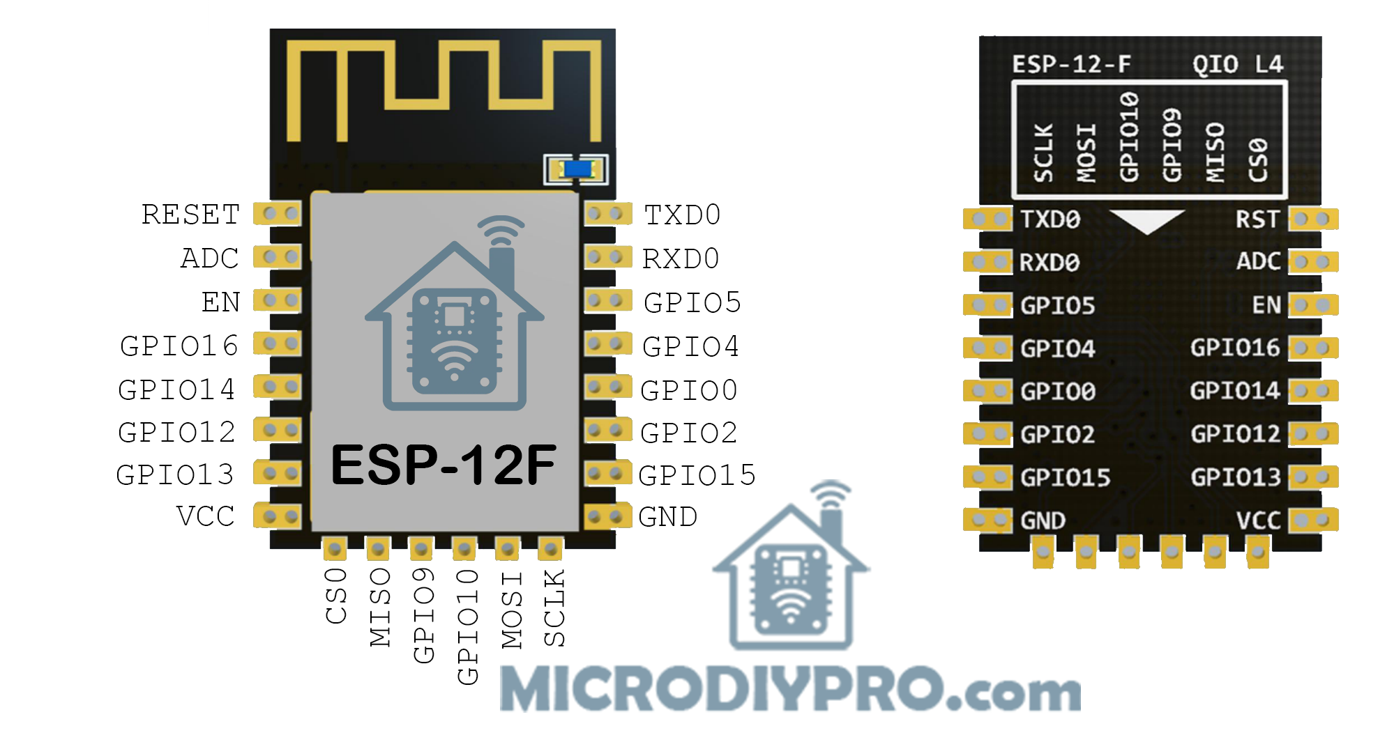
Considerations When Using ESP-12F Module
When designing with the ESP-12F, it’s important to know which pins and hardware peripherals are available and how to use them safely.
According to the ESP-12F datasheet from AI-Thinker, the SPI interface (pins 9–14) is not available for general use because it is connected to the embedded SPI flash chip.
Another popular ESP8266 module is the ESP-12S, which is a simplified version of the ESP-12F. The same pinout and GPIO guide in this section also applies to the ESP-12S. The only difference is that the ESP-12S does not expose the SPI interface, since it is already used internally and not required by most users. The same pinout information is also valid for the ESP-12E.
🔑 Differences between ESP-12F, ESP-12S and ESP-12E:
ESP-12E vs ESP-12F:
Pinout is identical.
ESP-12F has an improved PCB antenna (better range and stability).
ESP-12S:
Also same pinout.
Some versions remove the metal shield or change antenna design.
In rare cases, ADC input calibration may differ, but the pin layout is unchanged.
🔌 ESP-12F Interfaces
- UART0 (TX, RX): GPIO1 (TX), GPIO3 (RX). Used for programming and serial debugging.
- UART1 (TX only): GPIO2 can output TX1 (debug only, no RX).
- SPI (reserved for flash): GPIO6 (CLK), GPIO7 (MISO), GPIO8 (MOSI), GPIO11 (CS).
⚠️ Do not use these pins for general I/O — they are connected to the onboard flash chip. - I²C: No native hardware I²C, but software I²C can be mapped to most free GPIOs.
- PWM: Available on most GPIOs except GPIO16.
- ADC: Single ADC on GPIO17 (A0). Input range is 0–1V (bare chip). Many dev boards add dividers for 0–3.3V.
- Deep Sleep Wake-Up: Only GPIO16 can wake the chip from deep sleep (wired to RST).
🚫 Pins Reserved or Problematic
The following pins have special boot or internal functions:
- GPIO6–11: Used by SPI flash. Not available for programming.
- GPIO0, GPIO2, GPIO15: Bootstrapping pins — must be set correctly at reset:
- GPIO0: HIGH = normal boot, LOW = flash mode.
- GPIO2: Must be HIGH at boot.
- GPIO15: Must be LOW at boot.
- GPIO1 (TX), GPIO3 (RX): Used for UART0 (flashing & serial monitor). Usable but risky if you need serial.
- GPIO16: No PWM/I²C support. Special use for deep-sleep wake-up.
✅ Safe GPIOs for General Use
These pins are stable and recommended for digital I/O, PWM, I²C, etc.:
- GPIO4 (D2)
- GPIO5 (D1)
- GPIO12 (D6)
- GPIO13 (D7)
- GPIO14 (D5)
They have no boot restrictions and are reliable for most applications.
⚡ Bootloader Behavior
- GPIO1 (TX) prints boot messages at 74880 baud.
- GPIO2 and GPIO0 may briefly change state during boot.
- GPIO15 must always be held LOW at boot.
Avoid connecting relays or devices that could trigger unexpectedly during boot to these pins.
📑 ESP-12F Pinout Summary Table
| Pin | Name/Function | Notes |
|---|---|---|
| GPIO0 | Flash/Boot | HIGH = normal boot, LOW = programming |
| GPIO1 | TX0 | UART0 TX, prints boot logs |
| GPIO2 | GPIO / TX1 | Must be HIGH at boot |
| GPIO3 | RX0 | UART0 RX |
| GPIO4 | GPIO | Safe for general use |
| GPIO5 | GPIO | Safe for general use |
| GPIO6–11 | SPI Flash | Not available |
| GPIO12 | GPIO / HSPI MISO | Safe |
| GPIO13 | GPIO / HSPI MOSI | Safe |
| GPIO14 | GPIO / HSPI CLK | Safe |
| GPIO15 | Boot strap | Must be LOW at boot |
| GPIO16 | GPIO | No PWM/I²C, can wake from deep sleep |
| ADC0 | Analog In | 0–1V input only |
🧠 Key Hints for Using ESP-12F
- Program via UART0 (GPIO1/3). Keep USB-UART adapter connected for flashing.
- Check boot pins (0, 2, 15) wiring. Wrong levels = no boot.
- Avoid GPIO6–11 (SPI flash pins).
- For deep sleep: Connect GPIO16 → RST.
- ADC range is only 0–1V. Use a divider for higher voltages.
- Add pull resistors: GPIO0 (pull-up), GPIO2 (pull-up), GPIO15 (pull-down).
- Don’t drive loads directly from GPIOs. Max ~12mA. Use transistors/MOSFETs for relays, motors, LEDs.
If you need pinout guides or tips for other ESP8266/ESP32 modules, or have questions related to this tutorial, let me know in the comments below. Your feedback helps improve this guide with more practical information for future readers.

