In this tutorial, we’ll learn how to control a 4-wire DC fan using an ESP8266 and MicroPython. First, we’ll briefly explain the different types of DC fans—including 2-wire, 3-wire, and 4-wire models—and then move on to the step-by-step guide for controlling a 4-wire fan with the ESP8266.
Title in Other Languages
Below is the translated title of this tutorial for readers using non‑English languages. You can also use your browser’s translate feature to view the entire article in your language.
- German: Wie man einen 4‑adrigen PC‑Lüfter mit ESP8266 steuert (PWM‑ und Drehzahl‑Überwachung)
- French: Comment contrôler un ventilateur PC à 4 fils avec un ESP8266 (PWM et surveillance du régime RPM)
- Spanish: Cómo controlar un ventilador de PC de 4 hilos usando ESP8266 (PWM y monitoreo de RPM)
- Italian: Come controllare una ventola PC a 4 fili con ESP8266 (PWM e monitoraggio degli RPM)
- Portuguese (Brazil): Como controlar uma ventoinha de PC de 4 fios usando ESP8266 (PWM e monitoramento de RPM)
Tip: Right‑click anywhere on this page and choose “Translate to your language”.
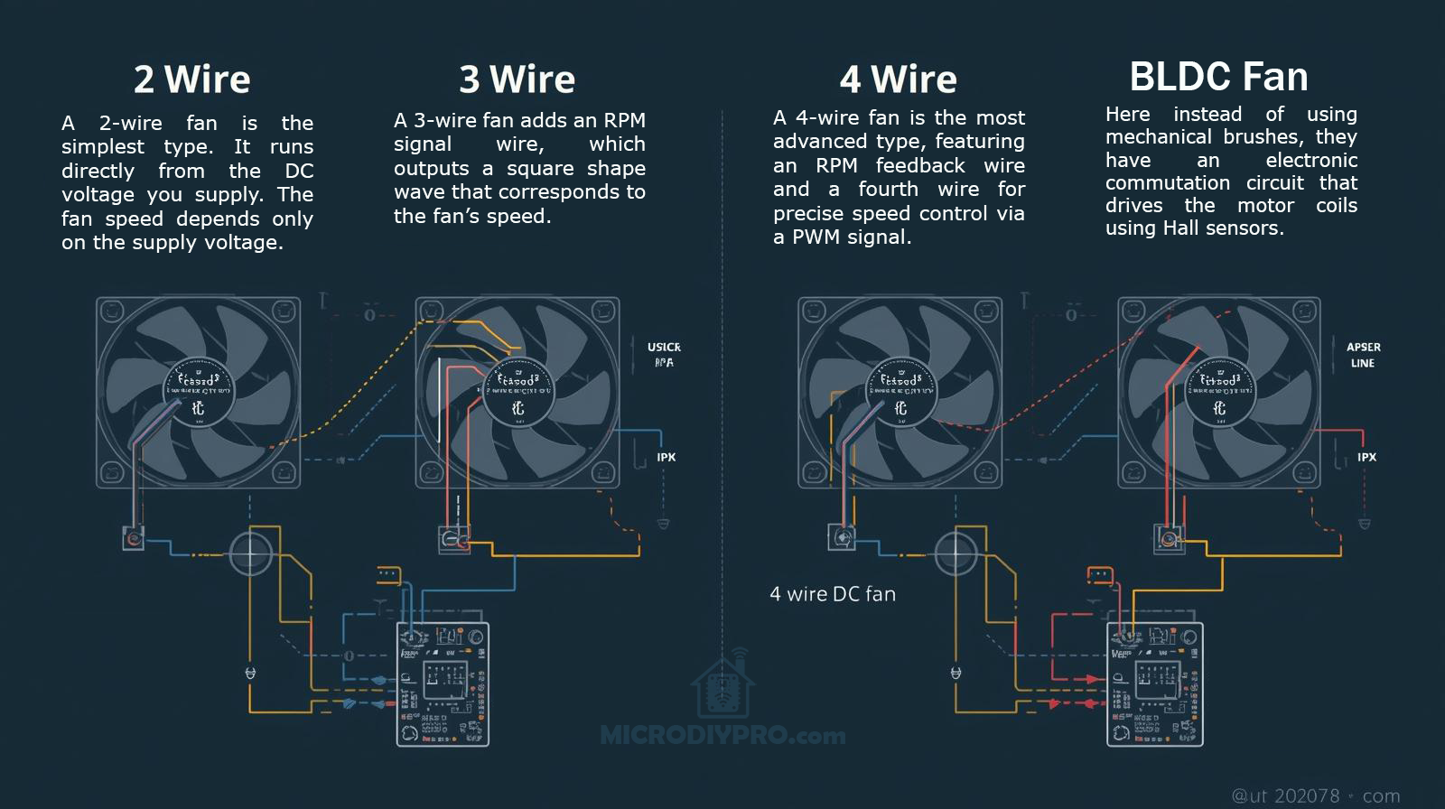
🌀 Understanding Fan Types: 2-Wire, 3-Wire, 4-Wire, and BLDC Fans
When working on electronic cooling or DIY projects with the ESP8266 or ESP32, it’s important to understand the differences between 2-wire, 3-wire, 4-wire, and BLDC fans. Each fan type offers different levels of control, feedback, and performance.
🧩 1. 2-Wire Fan (Basic DC Fan)
Wires:
- Red — +V (Power)
- Black — GND (Ground)
Explanation:
A 2-wire fan is the simplest type. It runs directly from the DC voltage you supply (for example, 5V or 12V). The fan speed depends only on the supply voltage — lower voltage means lower speed, and higher voltage means faster rotation.
Control Method:
You can use a transistor or MOSFET to switch the fan on/off or apply PWM on the power line, but some cheap fans may produce noise or not work well with PWM control.
Best for:
Simple cooling applications where precise speed control is not important.
⚙️ 2. 3-Wire Fan (With Tachometer Feedback)
Wires:
- Red — +V (Power)
- Black — GND (Ground)
- Yellow — Tachometer (RPM Signal)
Explanation:
A 3-wire fan adds an RPM signal wire, which outputs a square wave that corresponds to the fan’s speed. The microcontroller (like the ESP8266) can measure this signal to calculate the actual fan RPM.
Control Method:
Speed is still controlled by changing the supply voltage or PWM on the power line, but now you can read the actual speed for feedback.
Best for:
Projects that need speed monitoring, such as temperature-controlled systems or PC cooling mods.
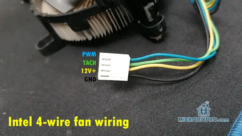
⚡ 3. 4-Wire Fan (PWM Controlled Fan)
Wires:
- Red — +V (Power, usually constant 12V)
- Black — GND
- Yellow — Tachometer (RPM feedback)
- Blue — PWM Control Signal
Explanation:
A 4-wire fan is the most advanced and most commonly used in computers. It keeps the power line constant (usually 12V), while the speed is controlled by a PWM signal (typically 25 kHz, 5V logic) sent through the blue wire. The fan’s internal circuit manages the motor speed smoothly and quietly.
Control Method:
You send a PWM signal from your ESP8266 (via a transistor or level shifter) to the control pin. The fan adjusts its speed without affecting the supply voltage.
Best for:
Smart cooling systems, IoT fan controllers, or any project that requires accurate and quiet fan speed control.
🔋 4. BLDC Fan (Brushless DC Fan)
Explanation:
All modern 3-wire and 4-wire fans are BLDC (Brushless DC) fans. Instead of using mechanical brushes, they have an electronic commutation circuit that drives the motor coils using Hall sensors.
This makes BLDC fans:
- More efficient and durable
- Quieter with less electrical noise
- Easier to control precisely with PWM
In short:
Every 4-wire PC fan is a BLDC fan, but not every BLDC fan has 4 wires.
✅ Summary Table
| Fan Type | Control Method | RPM Feedback | PWM Input | Suitable For |
|---|---|---|---|---|
| 2-Wire | Voltage Control | ❌ No | ❌ No | Basic cooling |
| 3-Wire | Voltage Control | ✅ Yes | ❌ No | Monitoring + control |
| 4-Wire | PWM Control | ✅ Yes | ✅ Yes | Smart, quiet control |
| BLDC | Electronic | ✅ Yes | ✅ Yes | High-efficiency systems |
How to recognize wiring of a 4-wire DC fan?
The first step is to determine the working voltage of the DC fan, which is usually printed on a label attached to the fan, engraved on the plastic body, or provided by the seller (especially for used or generic fans). For this tutorial, I used a 12V high-speed 4-wire BLDC fan. The fan wires are color-coded as Orange, Gray, Yellow, and Green.
I assumed the Gray wire as GND, and considered that the Orange or Yellow wire might be the positive power (+12V), since in many fans, yellow is often the power wire. I initially connected the power supply GND to Gray and +12V to Yellow, but the fan did not spin, and the current remained at 0 mA.
Next, I connected +12V to Orange, and the fan started at maximum speed, confirming the correct power wires. To control the fan speed, I used an ESP8266 with PWM at 1 kHz, testing which wire responds to PWM control. I connected Yellow to the ESP8266 PWM pin, and the fan speed became controllable via PWM.
Finally, the remaining Green wire is the RPM (tachometer) output, which can be read to monitor the fan speed.
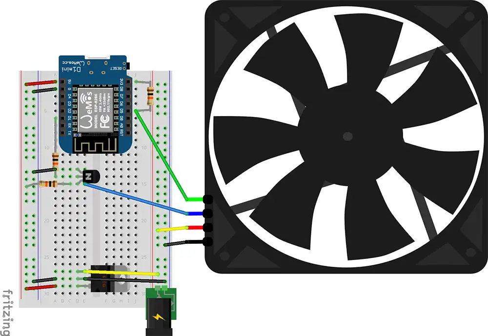
How to connect a 4-wire fan to ESP8266
In this section, we’ll test the PWM control of the 4-wire fan using the ESP8266 and MicroPython. I wrote a simple MicroPython script to verify the PWM signal, and it worked successfully. Using PWM on the ESP8266 with MicroPython is very straightforward. First, we need to select a PWM pin using the following command:
fan_pwm = PWM(Pin(5)) # Replace 5 with your chosen GPIO pin
Next, we define the PWM frequency and duty cycle. By default, the ESP8266 uses 1 kHz, but according to the Intel 4-wire PWM fan specification, we can increase it up to 25–40 kHz. At the beginning, we’ll set a 50% duty cycle. On the ESP8266, the duty range is 0–1023, so 512 equals 50%.
fan_pwm.freq(25000)   # 25 kHz as per Intel 4-wire PWM spec
fan_pwm.duty(512)     # 50% duty cycle (range 0–1023)
After testing the PWM, we can move on to measuring the fan RPM. To measure RPM, we’ll use an external interrupt on pin D5 (GPIO14).
A pull-up resistor between GPIO14 and 3.3V allows the ESP8266 to detect the falling edges of the tachometer signal.
The pulse_callback() function counts these pulses.
We then attach this function to the interrupt using tach_pin.irq().
pulse_count = 0

def pulse_callback(pin):
    global pulse_count
    pulse_count += 1

tach_pin.irq(trigger=Pin.IRQ_FALLING, handler=pulse_callback)
Since the fan produces two pulses per revolution, we divide the pulse count by 2 to calculate the number of revolutions. Because RPM means “revolutions per minute,” and we measure for one second, we multiply by 60 to convert seconds to minutes.
def measure_rpm(duration=1):
    global pulse_count
    pulse_count = 0
    time.sleep(duration)
    rpm = (pulse_count / 2) * (60 / duration)
    return rpm
Here’s the complete MicroPython code for controlling a 4-wire DC fan and reading its RPM using the ESP8266. You can simply copy and paste it into your Thonny IDE and run it.
from machine import Pin, PWM
import time

LED = Pin(2, Pin.OUT)
LED.off()

# --- Pin configuration ---
pwm_pin = Pin(5, Pin.OUT)                  # D1 = GPIO5 → PWM output to transistor base
tach_pin = Pin(14, Pin.IN, Pin.PULL_UP)    # D5 = GPIO14 → Fan tachometer input

# --- Setup PWM (fan speed control) ---
fan_pwm = PWM(pwm_pin)
fan_pwm.freq(25000)   # 25 kHz per Intel 4-wire PWM spec
fan_pwm.duty(512)     # 50% duty (range 0–1023 on ESP8266)

# --- Tachometer pulse counter ---
pulse_count = 0

def pulse_callback(pin):
    global pulse_count
    pulse_count += 1

tach_pin.irq(trigger=Pin.IRQ_FALLING, handler=pulse_callback)

# --- Function to measure RPM ---
def measure_rpm(duration=1):
    global pulse_count
    pulse_count = 0
    time.sleep(duration)
    # 2 pulses per revolution
    rpm = (pulse_count / 2) * (60 / duration)
    return rpm

# --- Main loop ---
try:
    duty = 512  # start at 50% duty
    while True:
        rpm = measure_rpm(1)
        print("Duty: {} / 1023  |  Fan Speed: {:.0f} RPM".format(duty, rpm))

        # Example: change fan speed
        duty = 980
        if duty > 1023:
            duty = 256
        fan_pwm.duty(duty)

except KeyboardInterrupt:
    fan_pwm.deinit()
    print("Stopped.")
I hope this tutorial was helpful in understanding how to control a 4-wire DC fan using ESP8266 and MicroPython and how to measure its RPM signal. If you have any questions or suggestions, feel free to leave a comment below.
What is fan RPM wire and how the pulses show the speed?
Understanding how the RPM (tachometer) wire works will help you measure fan speed correctly and design reliable circuits.
Let’s go step by step:
🌀 1. What the Tach (RPM) Wire Does
In a 4-wire fan, the tachometer wire (usually green) is a feedback signal from the fan’s internal controller. It tells you how fast the fan blades are rotating — but not by sending an analog voltage or direct RPM value. Instead, it sends digital pulses (a square wave) that correspond to the fan’s rotation speed.
⚙️ 2. Signal Characteristics
| Parameter | Typical value |
|---|---|
| Voltage type | Open-collector (transistor output, needs pull-up) |
| Logic level | 5 V or 3.3 V (depending on your pull-up resistor voltage) |
| Pulses per revolution | 2 pulses per revolution (for most fans) |
| Output frequency | Proportional to fan speed |
So when the fan spins, its internal Hall sensor or controller switches a transistor on/off twice per revolution of the blades.
This transistor pulls the tach wire low when active, and your pull-up resistor brings it high otherwise — forming a square wave.
📊 3. How Pulses Represent RPM
Let’s say your fan generates 2 pulses per revolution.
If you measure the frequency (number of pulses per second) of that signal:
RPM = (Pulses per second × 60) / Pulses per revolution
For 2 pulses/rev, this simplifies to:
RPM = Frequency (Hz) × 30
✅ Example:
-
Tach signal = 100 Hz
-
Each rev = 2 pulses → 100 Hz × 30 = 3000 RPM
🔌 4. Why It’s “Open-Collector”
The tach output inside the fan doesn’t actively drive the line high — only low. That’s why you must add a pull-up resistor (e.g., 10 kΩ) to bring it up to 3.3 V when inactive.
This design allows:
-
Multiple fans’ tach lines to be combined safely (in some systems)
-
Isolation between the fan’s 12 V logic and your microcontroller’s 3.3 V logic
🔍 5. Reading Tach Signal on Microcontroller
-
The ESP8266 or ESP32 pin detects edges (rising or falling) of this square wave.
-
You count how many edges (pulses) happen in a time window (like 1 second).
-
Then apply the formula to get RPM.
Your MicroPython code already does this:
rpm = (pulse_count / 2) * 60
because it counts all falling edges in 1 second (pulse_count = pulses/sec).
🧩 6. Typical Signal Timing (Visual)
Tach (green):  _|‾‾‾|_|‾‾‾|_|‾‾‾|_
                ↑    ↑    ↑
                |    |    |
                Each low pulse pair = 1 revolution
Each pair of low pulses corresponds to one full rotation of the fan blades.
✅ Summary
| Concept | Description |
|---|---|
| Output type | Open-collector square wave |
| Needs pull-up | Yes (typically 10 kΩ → 3.3 V) |
| Pulses per rev | Usually 2 |
| Frequency relation | 1 Hz = 30 RPM |
| Read method | Count pulses with microcontroller timer or interrupt |
Explanation about PWM wire and how to control it by ESP8266 PWM
This is the heart of 4-wire fan control 🔧🌀 You already control the RPM signal; now let’s understand and master the PWM control wire.
🧠 1. What the PWM Wire Does
The PWM wire (usually blue) is how the motherboard or controller tells the fan what speed to spin at.
-
It’s an input to the fan’s internal controller.
-
It carries a PWM (Pulse Width Modulation) signal — a fast square wave.
-
The duty cycle (how long the signal stays HIGH vs. LOW) tells the fan what percentage of its maximum speed to run at.
⚙️ 2. Electrical Characteristics (Intel PWM Fan Spec)
| Parameter | Typical Value |
|---|---|
| Signal Type | 5 V, open-collector compatible |
| Input Voltage Range | 0–5 V logic |
| Frequency | 25 kHz (±10%) |
| Logic “High” | > 2.1 V (fan detects this as ON) |
| Logic “Low” | < 0.8 V |
| Recommended Driver | Open-collector (NPN transistor) or open-drain |
👉 The fan already has an internal pull-up resistor to 5 V, so the controlling circuit (e.g. microcontroller) must pull the line LOW to modulate speed — not drive it high.
That’s why we use a transistor like 2N3904 or 2N2222 as a level shifter and open-collector driver.
⚡ 3. How PWM Controls the Speed
PWM = Pulse Width Modulation
-
The fan reads how long the signal stays high within each cycle (duty cycle).
-
Example:
-
100% duty → Full speed
-
50% duty → Half speed
-
20% duty → Very slow or stopped
-
| Duty Cycle | Fan Speed (approx.) |
|---|---|
| 0% | Off |
| 25% | ~25% speed |
| 50% | ~50% speed |
| 75% | ~75% speed |
| 100% | Full speed |
Each fan can respond slightly differently, but this is typical.
🔌 4. Circuit (Using ESP8266 + 2N3904)
    +5V (fan internal pull-up)
      |
      +----> PWM (blue wire)
                 |
                 | collector
               2N3904
                 |
                 | emitter
                 |
                GND (common with ESP8266)
                 |
ESP8266 PWM pin (e.g., D1) --[10 kΩ]--> base of 2N3904
✅ Notes:
-
The fan internally pulls the PWM line up to 5 V.
-
The 2N3904 transistor pulls it low according to ESP8266 PWM signal.
-
The ESP8266 never outputs 5 V, but that’s fine — the fan only cares about when it’s pulled low.
-
The 10 kΩ base resistor limits base current.
This way, the ESP8266’s 3.3 V PWM safely controls the 5 V fan input.