Title in Other Languages
- German: Intel 4‑Wire PWM Lüfter Spezifikation – 25 kHz PWM, Open‑Collector, Praxistests
- French: Spécification du ventilateur Intel PWM à 4 fils – 25 kHz PWM, collecteur ouvert, tests réels
- Spanish: Especificación del ventilador Intel PWM de 4 hilos – 25 kHz PWM, colector abierto, pruebas reales
- Italian: Specifica Intel della ventola PWM a 4 fili – 25 kHz PWM, open‑collector, test reali
- Portuguese (Brazil): Especificação do ventilador Intel PWM de 4 fios – 25 kHz PWM, open‑collector, testes reais
Tip: Right‑click anywhere on this page and choose “Translate to your language”.
1. Intel 4‑Wire PWM Fan Overview
Intel introduced the 4‑wire PWM fan interface to allow the motherboard to control fan speed without switching the 12 V supply.
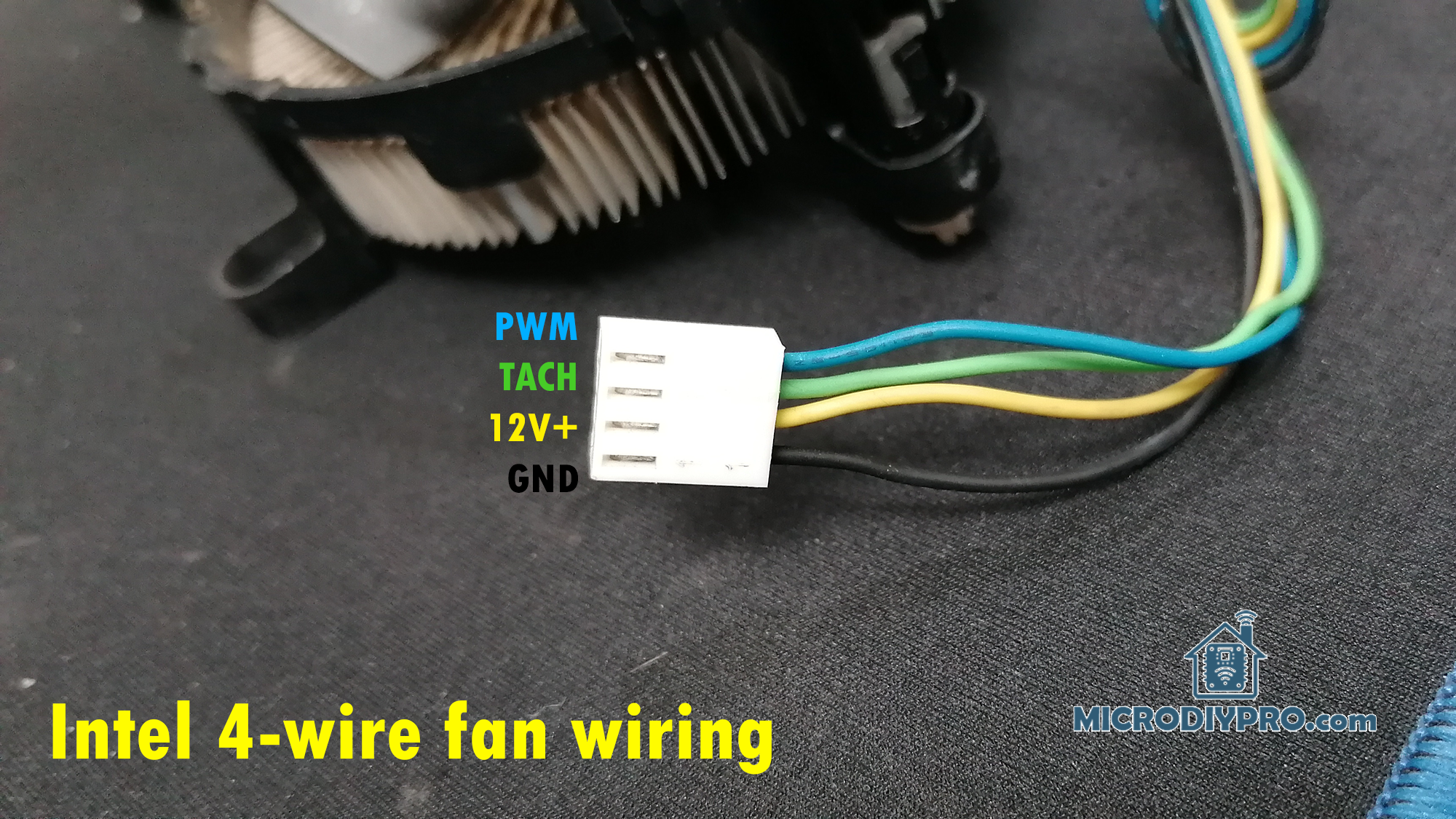
The four wires are:
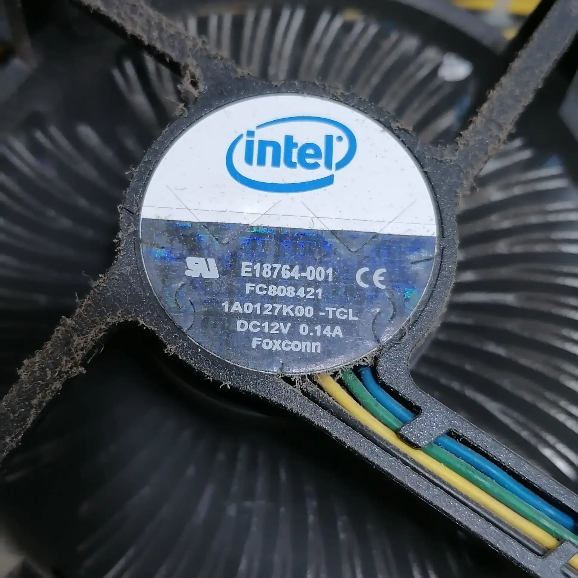
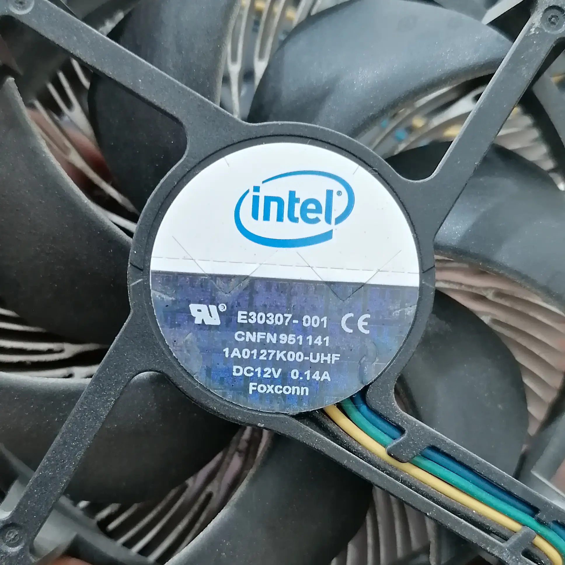
- Black – Ground (GND)
- Yellow – +12 V (constant power)
- Green – TACH output (open‑collector, 2 pulses per revolution)
- Blue – PWM control input
The PWM signal does not drive the motor directly. Instead, it is interpreted by a microcontroller inside the fan.
2. What the Intel Specification Actually Requires
According to Intel 4‑Wire Pulse Width Modulation (PWM) Controlled Fans Specification, Revision 1.3 (September 2005):
- PWM frequency: 25 kHz ±10%
- PWM signal type: Open‑collector / open‑drain
- PWM pull‑up voltage: Provided internally by the fan (≈5 V)
- Required minimum speed: ≤ 30% of maximum RPM
Most importantly, Intel defines the low‑duty region as follows:
Below the minimum PWM duty cycle, fan behavior is “Undetermined”.
This means Intel does not guarantee:
- Linear speed control
- Fan stop at 0% PWM
- Any specific RPM behavior
3. Common Misconception: “0% PWM Stops the Fan”
Many hobbyists assume that:
0% PWM = Fan OFF
This assumption comes from modern PC fans, laptops, and GPUs. However, legacy Intel‑spec fans were never required to support 0‑RPM operation.
In those fans:
- 12 V is always present on the motor
- The fan firmware enforces a minimum safe speed
- 0% PWM usually means “minimum allowed RPM”
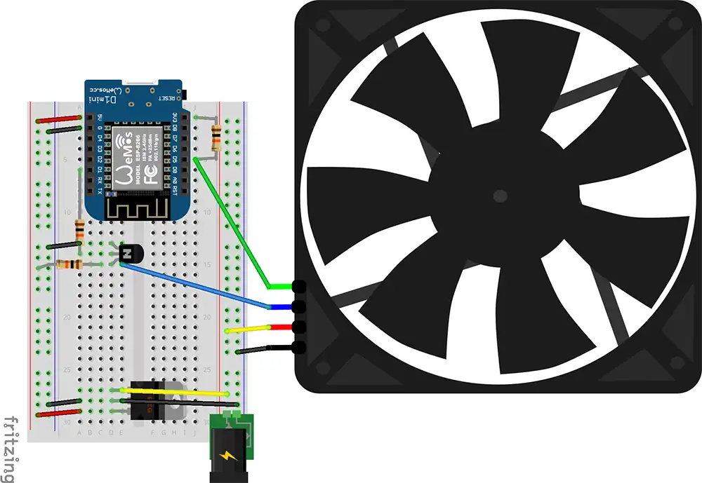
4. Test Setup
All experiments were performed using:
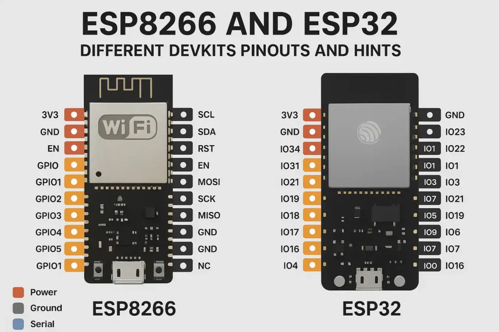
- ESP8266 microcontroller
- 25 kHz open‑drain PWM output
- Direct +12 V fan supply
- RPM measured via TACH output
The following was verified experimentally:
- PWM pin floats high when disconnected (~3.5–4 V)
- Connecting PWM to GND lowers speed but does not stop the fan
- Disconnecting the TACH wire has no effect on fan behavior
Refer to my tutorial How to Control a 4‑Wire PC Fan Using ESP8266 (PWM + RPM Monitoring Guide) if you want to test your Intel 4‑wire fans easily.
5. Experimental Results
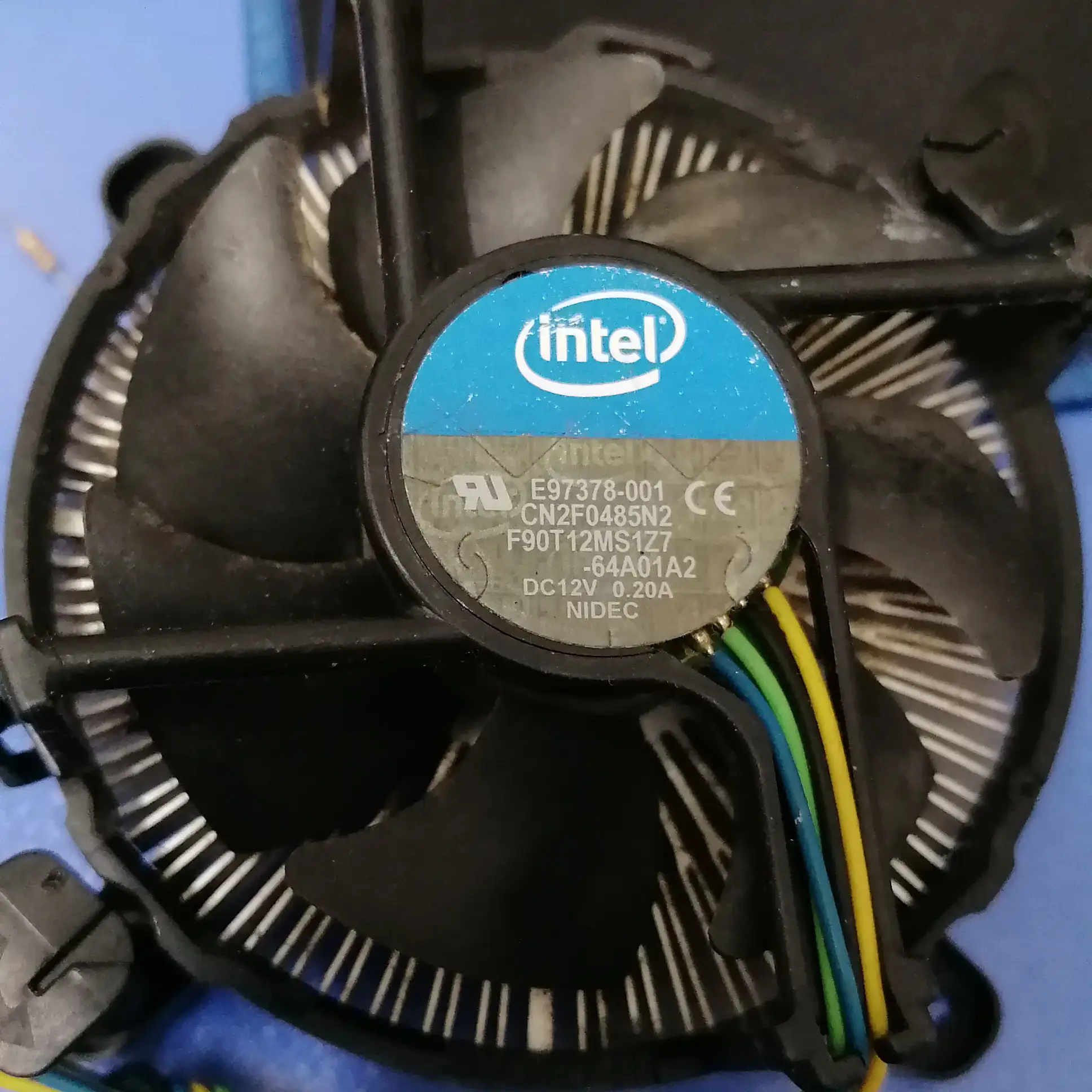
5.1 DELTA E97378‑001
- 0% PWM: ~990 RPM
- 30% PWM: ~1290 RPM
- 50% PWM: ~1500 RPM
- 100% PWM: ~1980 RPM
This fan enforces a clear minimum speed and never stops.
5.2 NIDEC E97378‑001 (Used Fan)
- 0% PWM: 1140–1380 RPM
- 30% PWM: 1200–1500 RPM
- 50% PWM: 1200–1500 RPM
- 65% PWM: 1590–1890 RPM
- 80% PWM: 1830–2160 RPM
- 100% PWM: 2500–2800 RPM
This fan shows a wide low‑PWM dead zone and unstable RPM, likely influenced by age and wear.
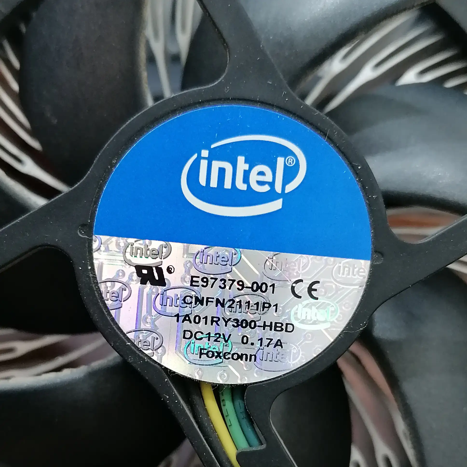
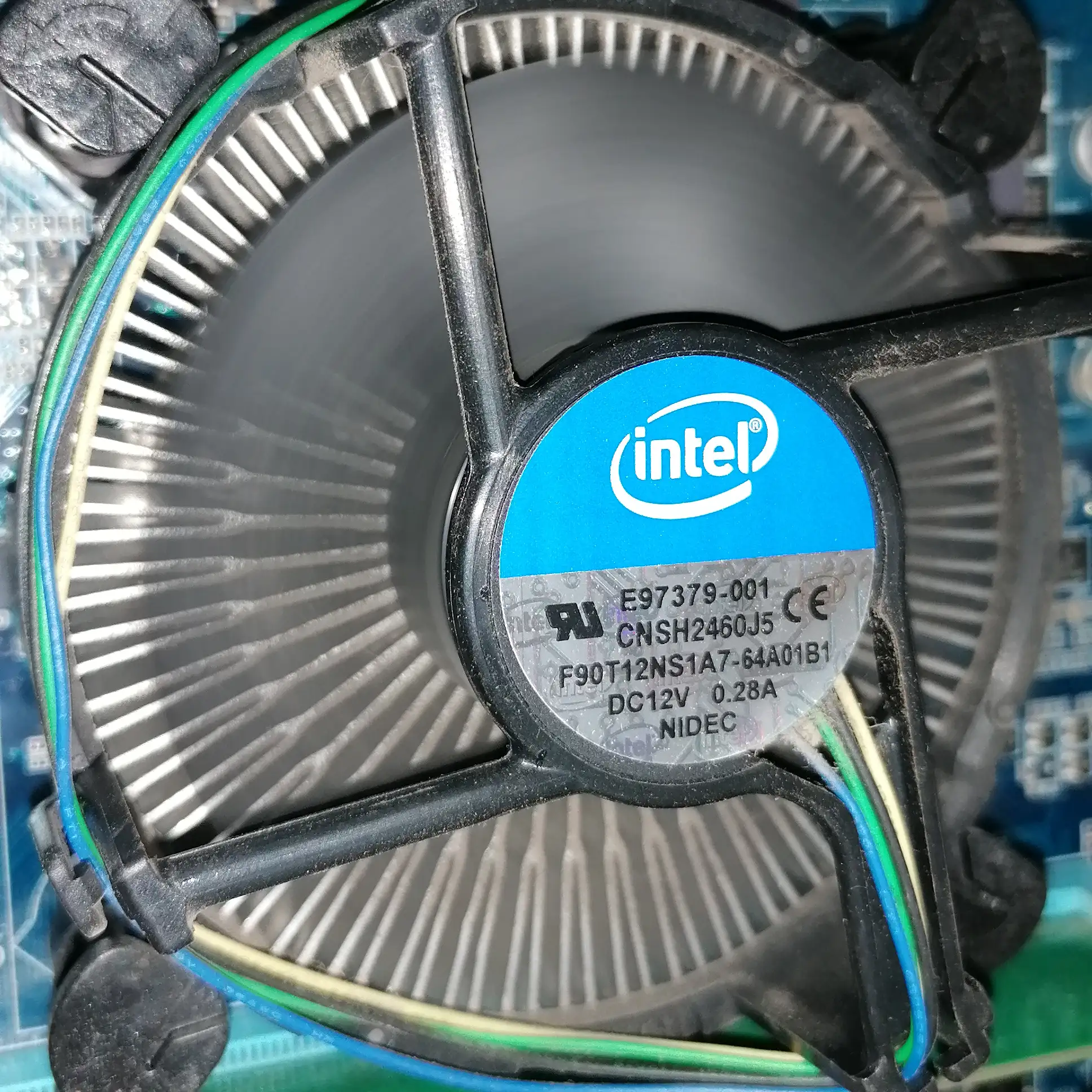
5.3 FOXCONN E97379‑001
- 0% PWM: 750 RPM
- 15% PWM: 840 RPM
- 25% PWM: 900 RPM
- 50% PWM: 1200 RPM
- 75% PWM: 1500 RPM
- 100% PWM: 1700 RPM
This fan provides smooth low‑speed control but still does not stop at 0% PWM.
For example, while testing the NIDEC E97379‑001 fan, I observed that the fan does not respond immediately to changes in the external PWM signal after power is applied. Instead, the fan appears to perform an internal start‑up and self‑test sequence that lasts for approximately 15 seconds.
During this time, the fan behavior is controlled entirely by its internal controller and is largely independent of the PWM duty cycle applied on the control pin. PWM changes made during this interval do not produce an immediate or predictable effect on RPM. Only after the internal initialization sequence completes does the fan begin to properly track the external PWM signal.
This behavior is likely related to internal rotor alignment, stall detection, motor characterization, and safety checks implemented by the fan manufacturer. Such logic ensures reliable startup, prevents false stall detection, and guarantees adequate cooling immediately after power‑on, even if the PWM signal is unstable or incorrectly configured.
Consequently, from a system design perspective, this explains why some Intel‑spec fans briefly run at a fixed or elevated speed after power‑up and why microcontroller‑generated PWM may appear to be ignored during the first several seconds of operation. This delay is normal for certain legacy and server‑grade fans and should be accounted for in embedded‑control applications.
6. Why Fans Start at Full Speed Without PWM
When the PWM pin is left disconnected:
- The fan’s internal pull‑up pulls it HIGH
- The signal is interpreted as 100% duty
- The fan performs an internal startup sequence
This behavior is intentional and ensures reliable cooling even if PWM control fails.
7. Why Disconnecting TACH Has No Effect
The TACH pin is:
- An output only
- Open‑collector
- Used for monitoring RPM only
The fan does not rely on the TACH signal for motor control. Disconnecting it does not change speed or PWM behavior.
8. Frequently Asked Questions
Does 0% PWM stop an Intel 4‑wire fan?
No. According to the Intel 4‑Wire PWM fan specification, behavior below the required minimum duty cycle is “Undetermined.” Many legacy Intel‑spec fans, as shown in our real‑world tests, continue running at a minimum RPM even when commanded with 0% PWM.
Why is 25 kHz PWM required?
The Intel specification mandates a 25 kHz (±10%) PWM control signal to avoid audible noise in the human range (below 20 kHz) and to ensure the fan’s internal controller correctly filters and interprets the signal.
Can a microcontroller drive the PWM pin directly?
The PWM signal must be generated by an open‑collector or open‑drain output (like a MOSFET or a specialized pin on the ESP8266/MicroPython). Driving the fan’s PWM pin with a standard push‑pull logic signal could damage the fan’s internal circuitry, which relies on its own 5V internal pull‑up.
9. Key Takeaways
- 0% PWM does not guarantee fan stop
- Minimum RPM is enforced internally by the fan firmware
- Low‑PWM behavior is vendor‑specific and intentionally undefined by Intel
- Modern 0‑RPM fans use additional, non‑spec firmware logic
- Legacy Intel PWM fans prioritize safety and reliable cooling
10. Conclusion
Intel’s 4‑wire PWM specification was designed for safe and reliable cooling, not silent operation or fan‑off states. Real‑world testing confirms that many fans continue running at a minimum speed even at 0% PWM. Always test the specific fan model you plan to use in your embedded projects.
Understanding this distinction prevents incorrect assumptions in embedded and DIY projects.
For official technical documentation, refer to Intel’s official website.